Vertical Orientation System (VOS) Project
I started my vertical orientation system project at the beginning of 2022. It uses forward mounted canards to control the spin and point the rocket vertically.
The acronyms VOS (Vertical Orientation System), VOC (Vertical Orientation Control), and VTS (Vertical Trajectory System) are all used to describe systems that steer the the rocket to a vertical orientation. Technically, pointing the rocket vertically does not necessarily result in a vertical trajectory, but the term VTS was first coined by David Ketchledge in an article in the July/August 1993 issue of High Power Rocketry magazine, and then used again later by Steve Ainsworth in a March 1999 article in High Power Rocketry, both for early attempts at systems that pointed the rocket vertically. Because of this precedent, I started by using the VTS acronym to describe this project, hence the name of my test rocket, VTS-1, but I am now using VOS as the acronym as it more accurately represents what my control system is actually doing.
This is an ongoing project that I will continue to document here. The first flight of VTS-1 was on May 21, 2022, and as of May, 2025, the VTS-1 Rocket has made 15 flights. The only original part from the first flight is the nose cone. All the other parts have evolved over the 15 flights.
The design philosophy for VTS-1 was to make the test rocket large enough to easily accommodate the VOS control unit, while making it no larger than necessary to keep the cost to build and fly it as low as possible. This makes it easy to fly often to collect new flight data and iterate on the design as needed to make improvements - a fast cycle time approach.
I will be writing several papers to describe the rocket dynamics modeling, servo motor dynamics modeling, and control system designs for VTS-1. There is much to describe, so this will take a while. The first two papers are available on the Papers page. I will be posting the remaking papers to this web site as they are completed.
This page covers the design of the VTS-1 rocket. Click here to go to the simulation and flight results page.
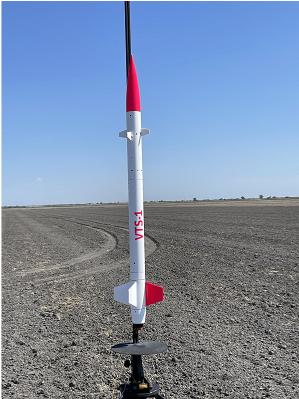


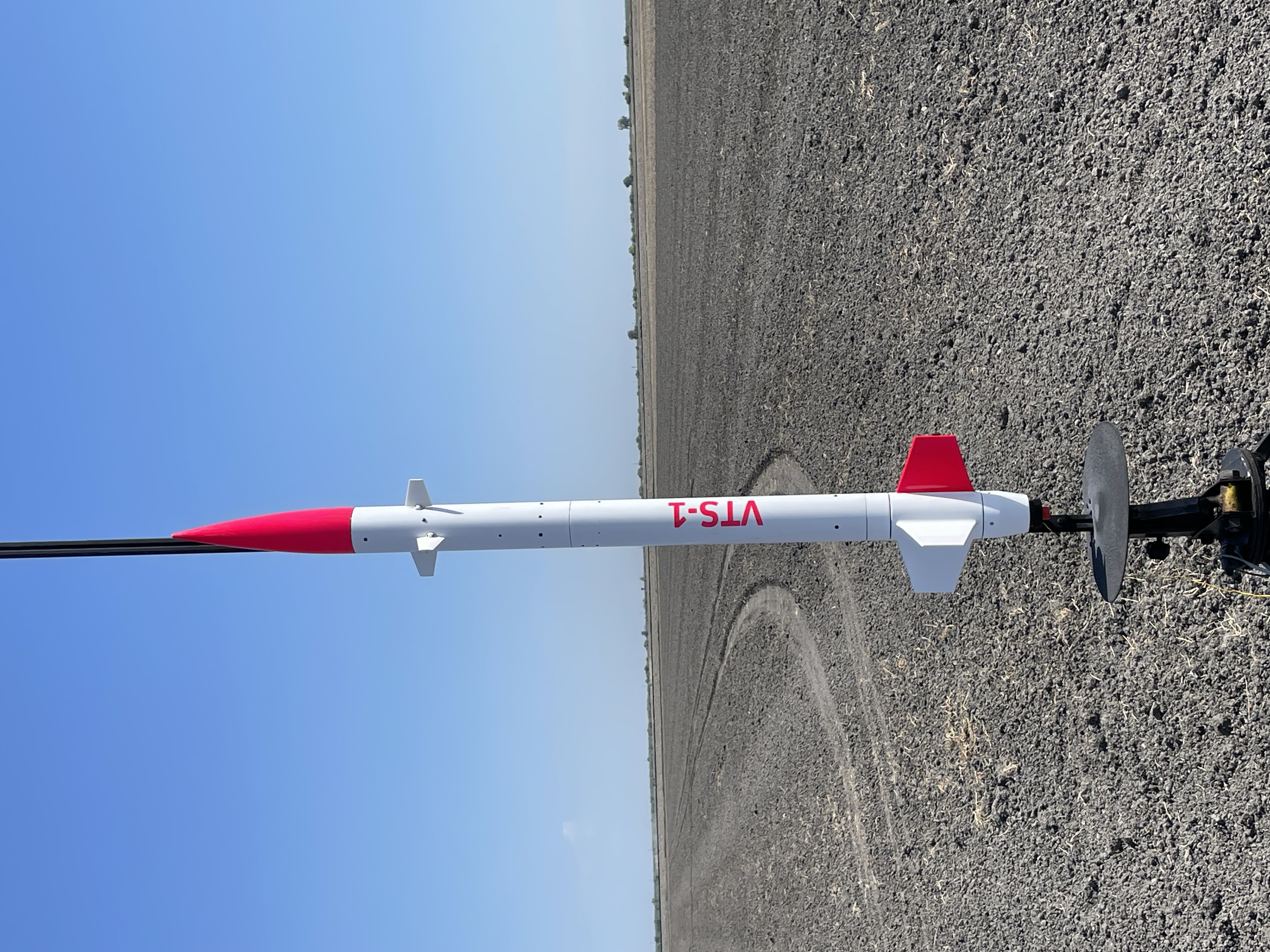
The VTS-1 is a 3 in diameter, 59 in long rocket weighing 8 lbs. 3 inches is the minimum diameter that makes it practical to fit the canard control unit. The construction is fiberglassed PML phenolic tube. The nosecone is custom fabricated fiberglass.
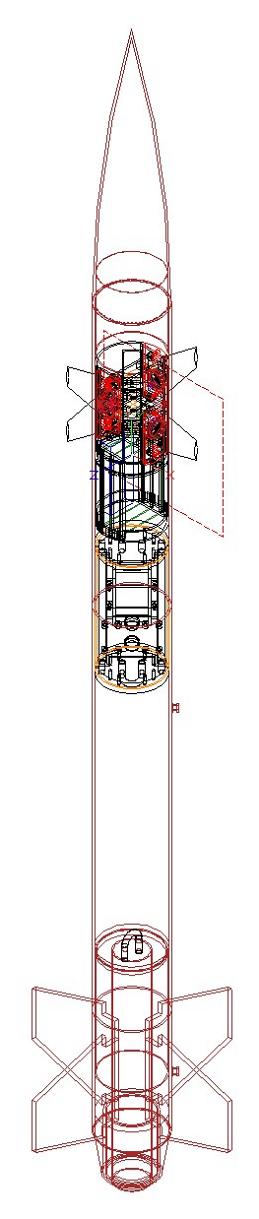
The canard control unit is located near the front of the rocket. A separate ebay containing two Altus Metrum Easy Mini altimeters sits behind the canard control unit. I do not want to mix critical flight functions like parachute deployment with a control system that is in active development. The rocket separates at the midpoint, and the forward and rear sections each come down separately on their own parachute to avoid the two sections hitting each other and damaging the canards. The nosecone holds a GPS tracker.
Flights 1-7 flew on an AT I-211W motor, and flights 8-15, after the spin can was added, flew on an AT J350-W or AT J415-R.
The canard control system is a self contained unit that slides down into the forward body tube and is fastened by four bolts through the body tube. The canards bolt on from the outside of the rocket once the unit is mounted in the body tube.
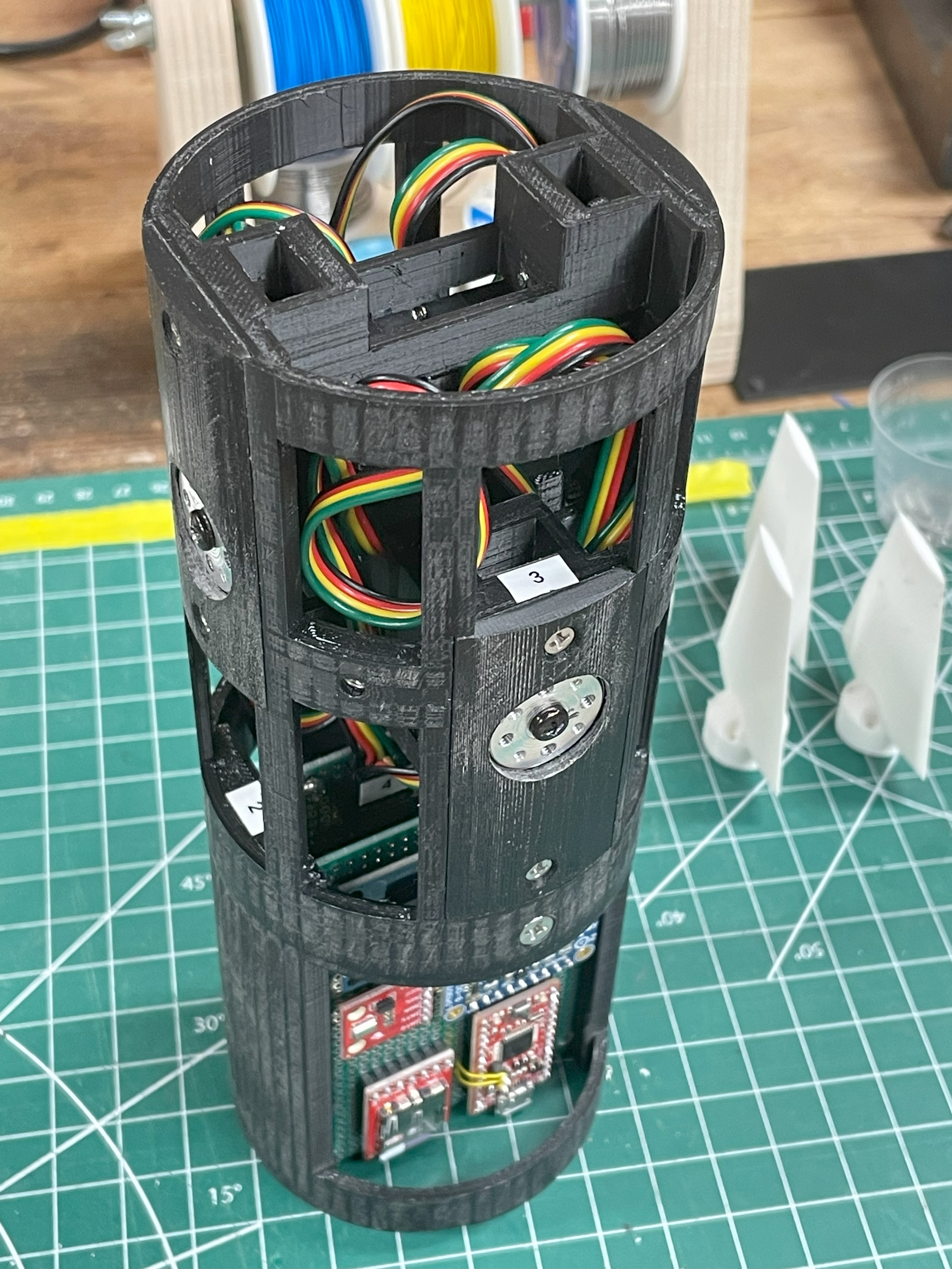
The unit is 3D printed and consists of a forward frame that holds the 4 servo motors and a separate rear frame that holds the electronics. The two frames bolt together to form a single self contained unit.
Because it is self contained and can be completely removed, it is easy to program and test on the workbench. It has several test modes. To test in flight mode, the unit is placed in a vacuum chamber to trigger and cycle through the prelaunch, launched, apogee/descent, and landed states.
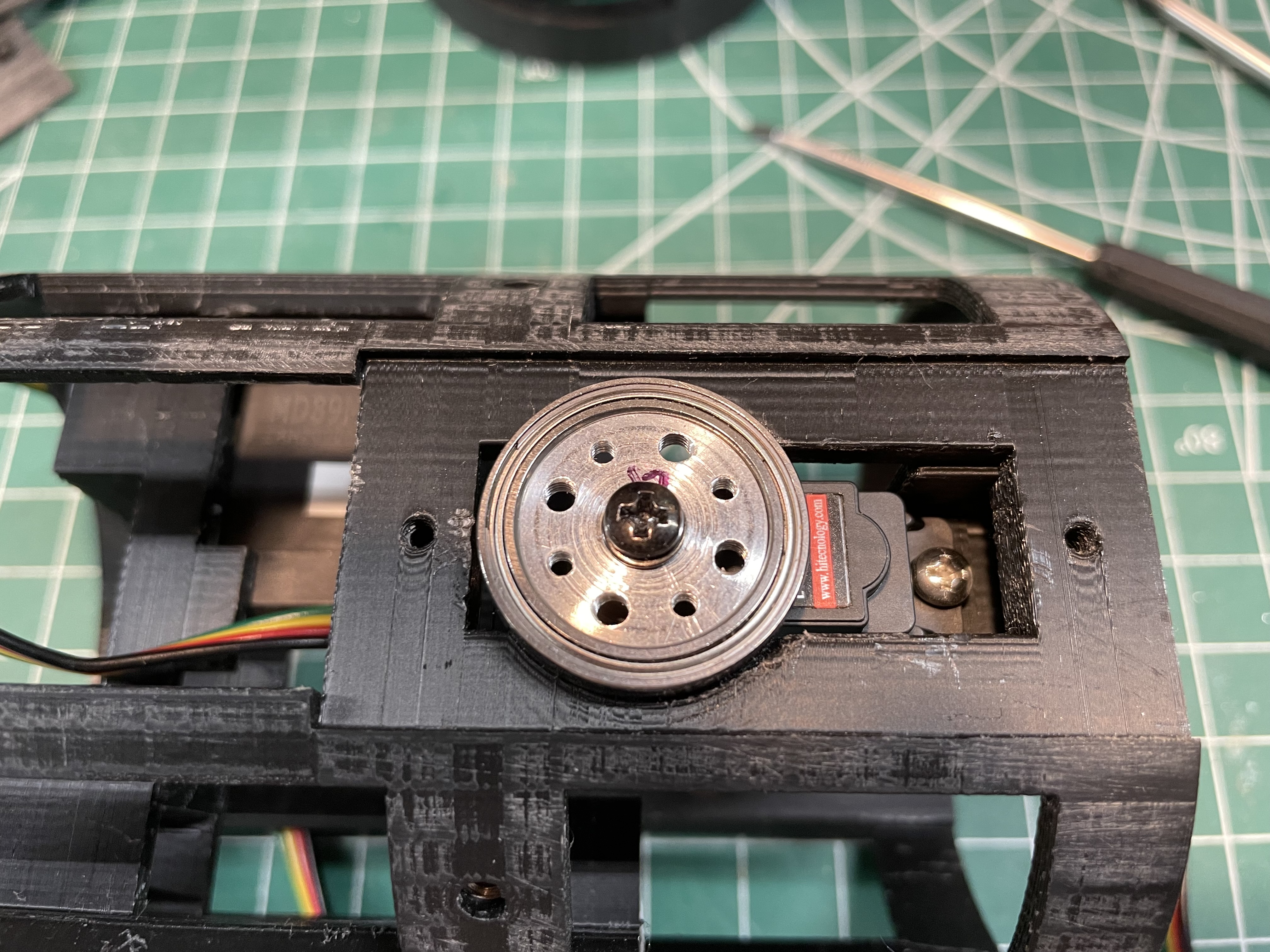
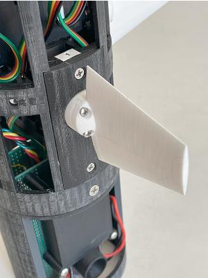
This picture is of the 4th generation of the canard control unit which is currently in use.
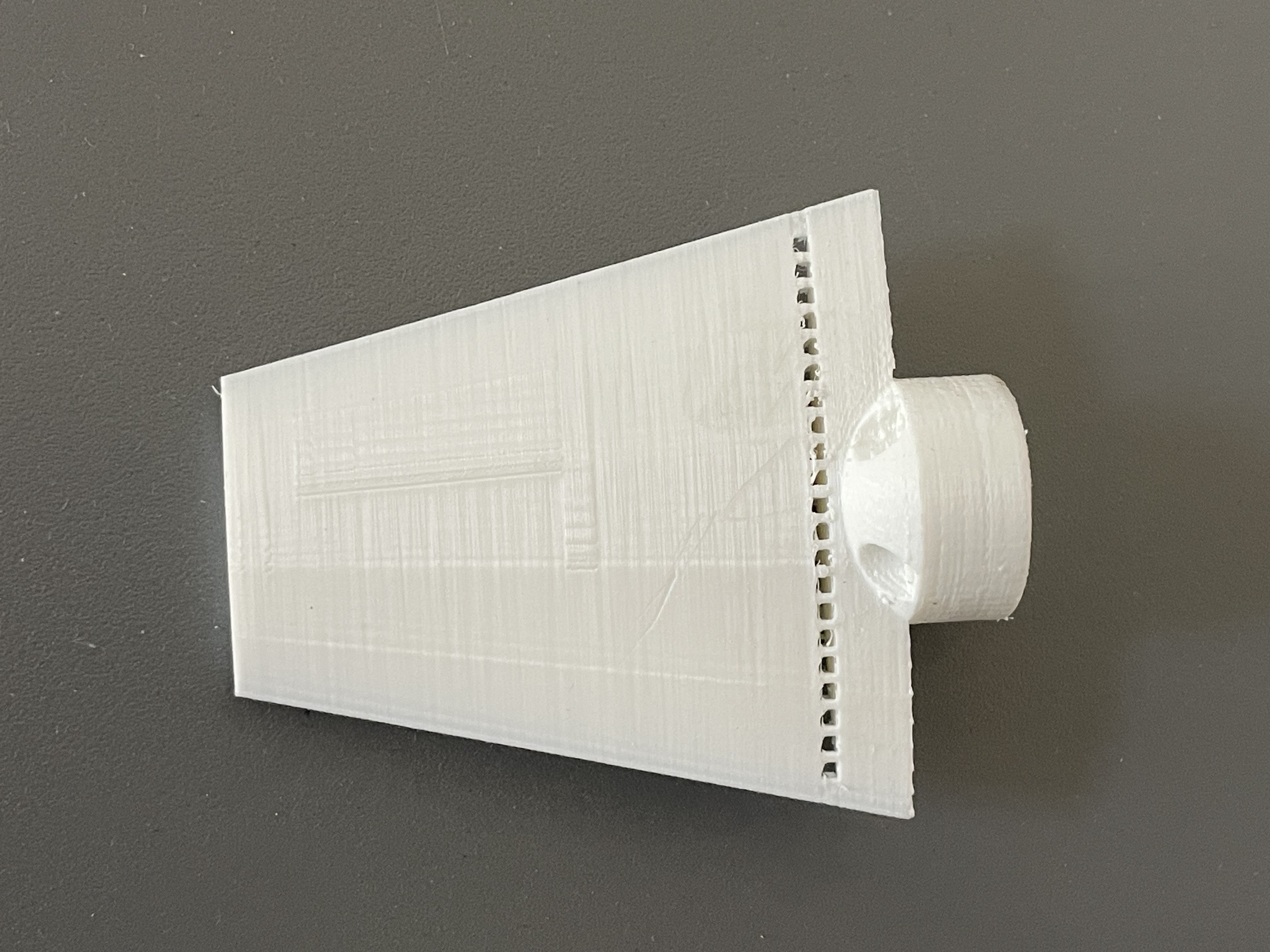
The 3D printed canards are bolted onto the servo hub from the outside. If the unit is installed in the rocket, the canards are bolted on after the unit has been bolted into the body tube.
The servo motors used in the 4th generation of VOS hardware for flights 11-15 are Hitec MD89MW-CAN 13 mm servo motors. These are programmed and controlled via a CAN bus rather than a PWM signal used by standard RC servro motors. These servo motors are used because their servo controller uses a much higher sample rate and the control loop bandwidth is higher than the standard PWM RC servo motors. This makes it much easier to design the VOS control loops.
To protect the servo motor shaft and bearings from the impact of landing, the aluminum servo hub is supported by a 3/4"x1" bearing, housed within a recess in the frame and cover plates.
Despite the bearing supporting the outside of the servo hub, I did bend the shaft of a servo motor on one landing. After adding breakaway perforation holes to the canards, the canards break off on a hard landing, rather than bend the servo motor shaft. There have been no bent shafts since adding the holes.

Canards mounted forward of fixed fins are not effective for controlling roll. The when the canards are rotated at an angle to the direction of the oncoming airstream, the air leaves the canards at a slight angle. When the fins then fly through that airstream, it appears that the fins are at a non-zero angle of attack to the airstream creating a lift force. Due to the symmetries involved, a roll torque is then generate by the fins that is in the opposite direction of the roll torque generated by the angled canards, which reduces the effectiveness of the canards for roll control. In extreme cases, the torque of the fins can be greater than the torque generated by the canards, reversing the direction of control. Again, due to the symmetries involved, this effect does not negatively impact the use of forward canards for pitch or yaw control (tilt) control. This is why most forward canard controlled missiles only use the canards to control pitch an yaw, and another method, like spinerons on the fins, or a rate controlled spinning mass to control roll.
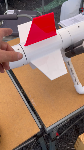
A technique to allow using forward canards for roll control is to use free rolling fins", or "spin can". The fins are not controlled, they are just allowed to rotate freely relative to the body of the rocket. This way, they cannot impart a counter roll torque to the rocket, so the forward canards are fully effective for roll control. I learned about spin cans from Jim Jarvis who uses them on his VOS rockets. The earliest reference I found for a free rolling fin unit dates back to a NASA paper from 1978.
Click here for spin can video
Other techniques for combined roll and tilt control include using fin tabs or canards behind the fins. Fin tabs require embedding the servo motors in the fins, and have a disadvantage because the pivot point cannot be placed at the center of pressure of the fin tab, which can result in high torques on the servo motor during high speed fligths.
Placing the canards behind the fins requires having an outer diameter of the rocket large enough to fit the servo motors between the motor tube and outer body tube, or using linkages between the canards and servo motors if the servo motors are place ahead of the rocket motor. With linkages, it would be difficulet to maintain the fraction of a degree of backlash required of the system.
Either of these alternate techniques also means the control unit is not a stand alone self contained system like the VTS-1 system. For these, the conttol mechanics have to be integrated into the rocket body. This makes testing and design changes more complicated. The forward canard control unit along with a spin can appears to be the simplest and most practicle of the three options.
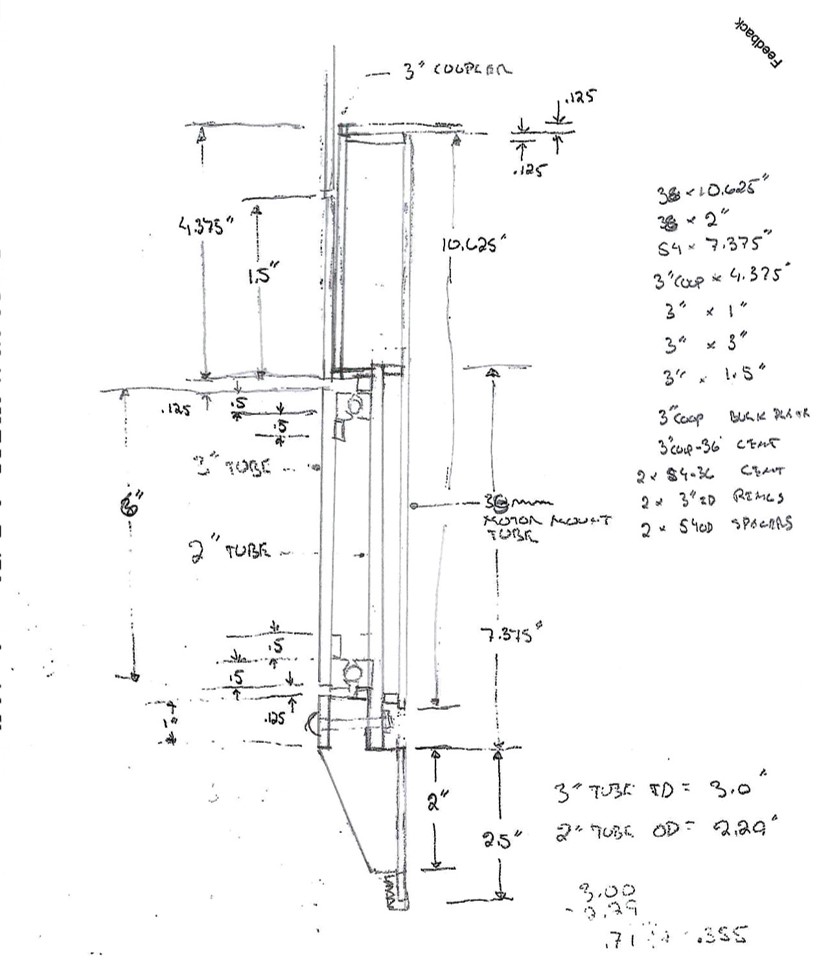
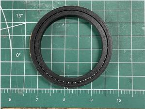
The spin can is built using three body tube diameters. For VTS-1, the inner motor tube is 38 mm (1.5"), the intermediate tube is 2", and the outer body tube is 3" . The bearing unit sits between the 2" and 3" tubes, giving about 1/2 in for the height of the bearing unit.
The bearing units are retained by rings attached to the intermediate tube and the outer tube. The removable tail cone and spacer ring locks eveything in place. The bearing units slide into place and are not glued to the tubes. The unit can be disassembled by removing the tail cone in case the bearing units need to be replace. The three tube design allows room for the tail cone retaining nut.
This spin can design uses standard diameter body tubes with plenty of room for the bearing race unit. A near minimum diameter spin can can be constructed if custom diameter body tubes are made and the tubes are used as the bearing races.
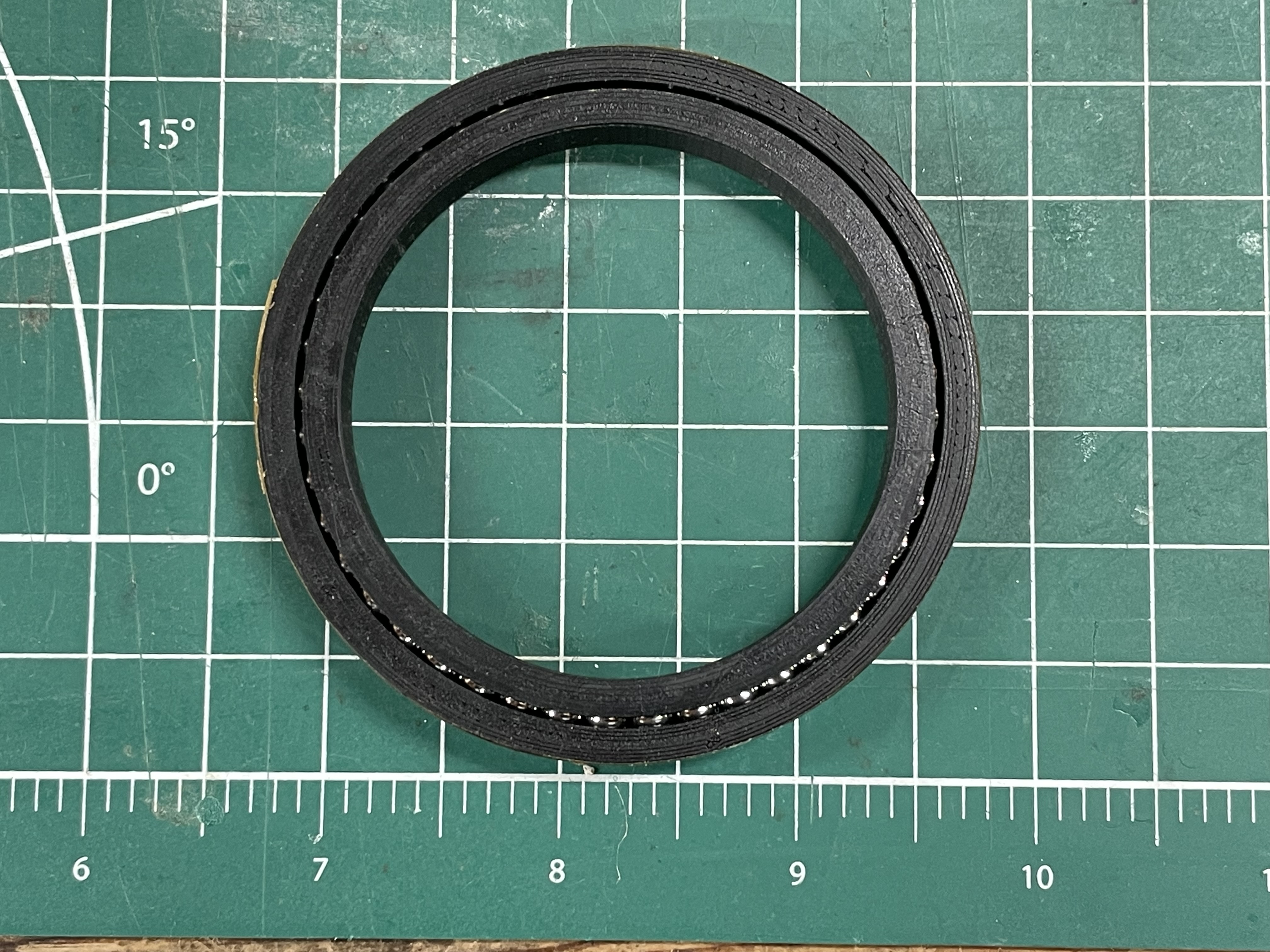
The bearing units are 3D printed to fit the inner diameter of the outer tube and the outer diameter of the middle tube. They use 3/16" steel bearing balls. The outer race ring has a top and bottom part. The balls are placed between the inner race ring and the outer bottom half race ring, and then the top half of the outer race ring is inserted and glued to the bottom half. They are printed at 0.05 mm layer height and they work very smoothly.
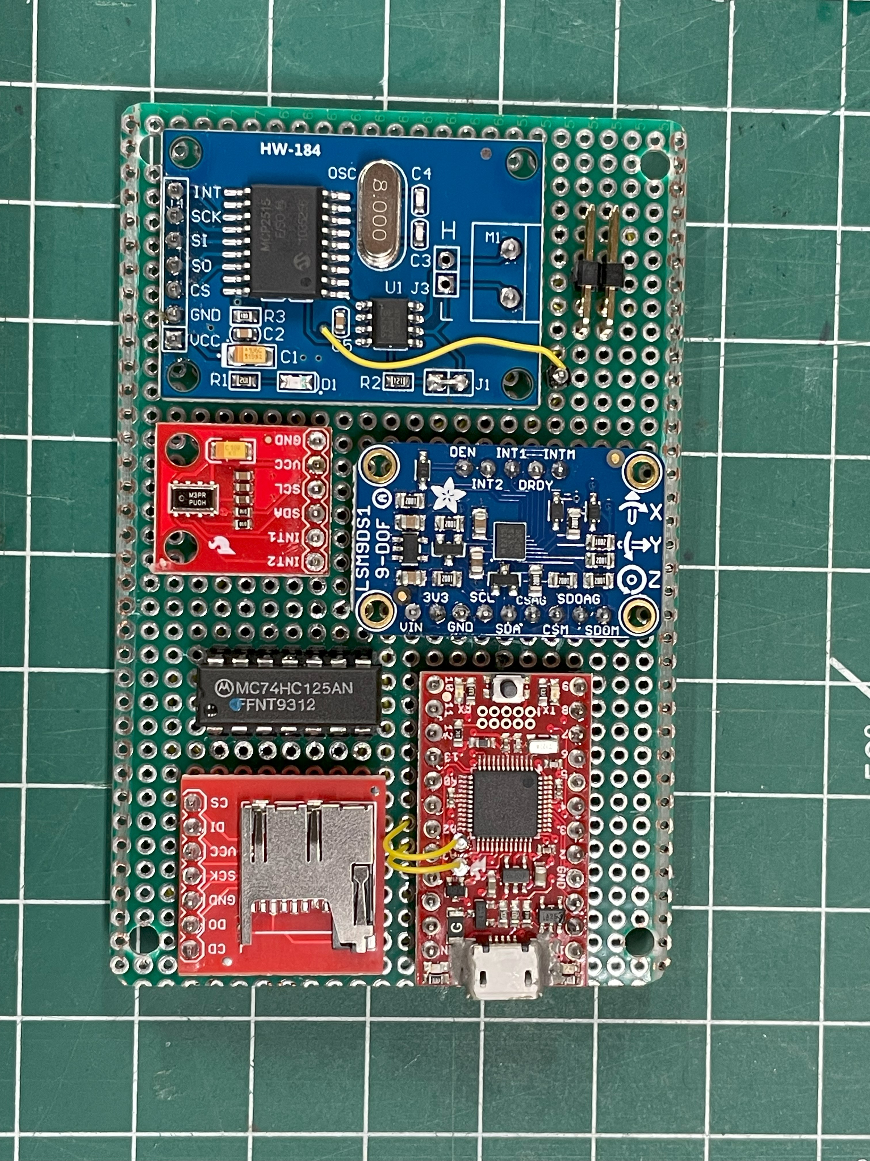
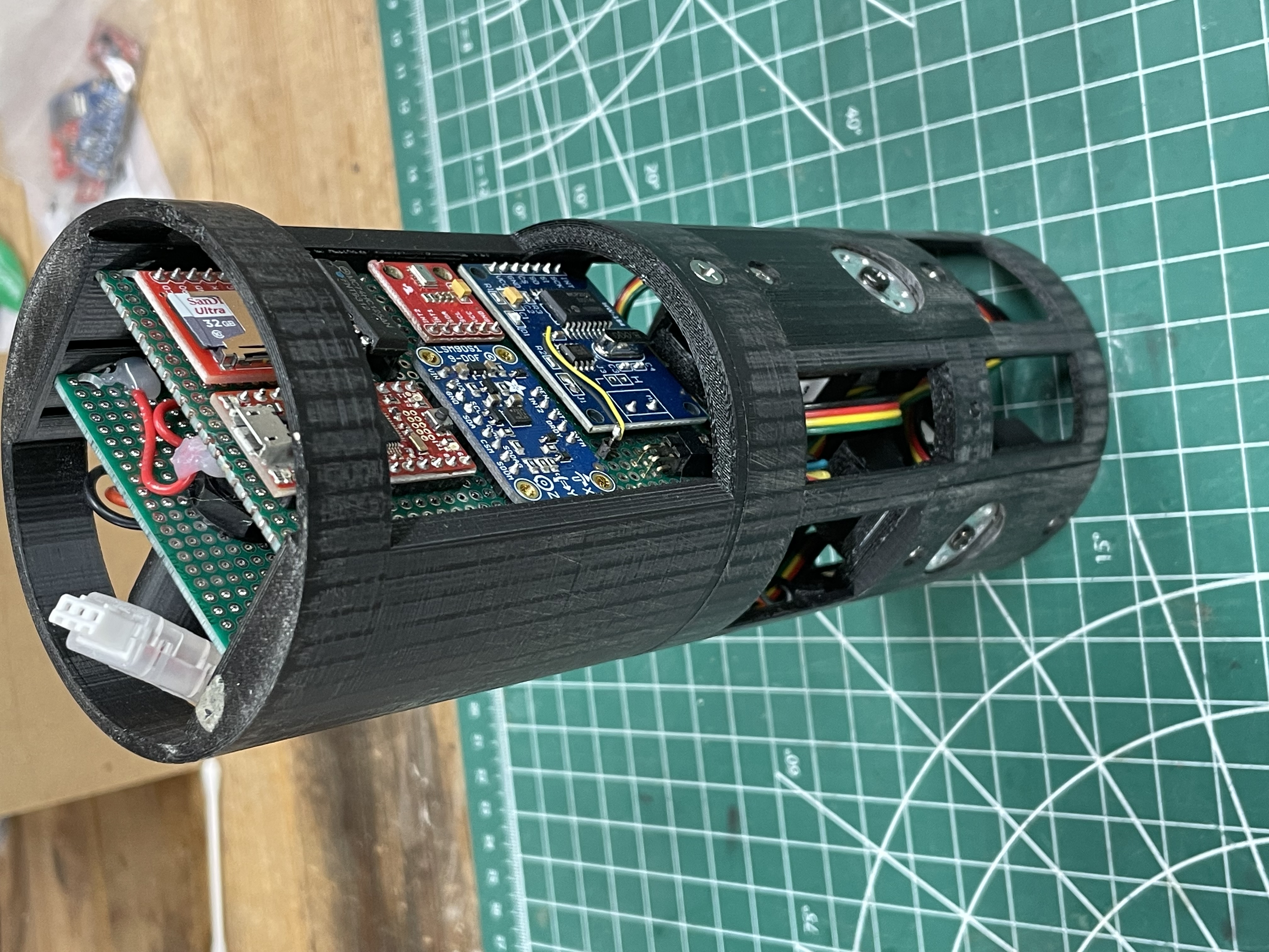
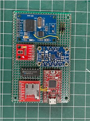
This is the 4th revision of the controller board currently being used. It includes the following parts:
* Sparkfun Atmel SAMD21 Arduino controller
* Freescale MPL3115A2 Precision Barometric Altimeter
* ST LSM9DS1 3 axis Accelerometer, Gyroscope, Magnetometer
* Microchip MPC2515 CAN bus controller with SPI interface
* 74LS125 tri-state buffer
* microSD card reader
The accelerometer and magnetometer are used to implement a tilt compensated compass to determine the absolute orientation of the rocket on the launch pad when the unit is first turned on. This provides the initial values for the Euler's angles. Once launch occurs, just the gyroscope is used to determine changes in the orientation of the rocket.
The barometric sensor is used to determine launch (along with the accelerometer), apogee, and landing, as well as providing the flight altitude profile.
Flight data is recorded to a microSD card during the flight. A circular buffer records the one second before launch and is written to the SD card at the end of the flight.
The CAN bus controller is the interface to the servo motors.
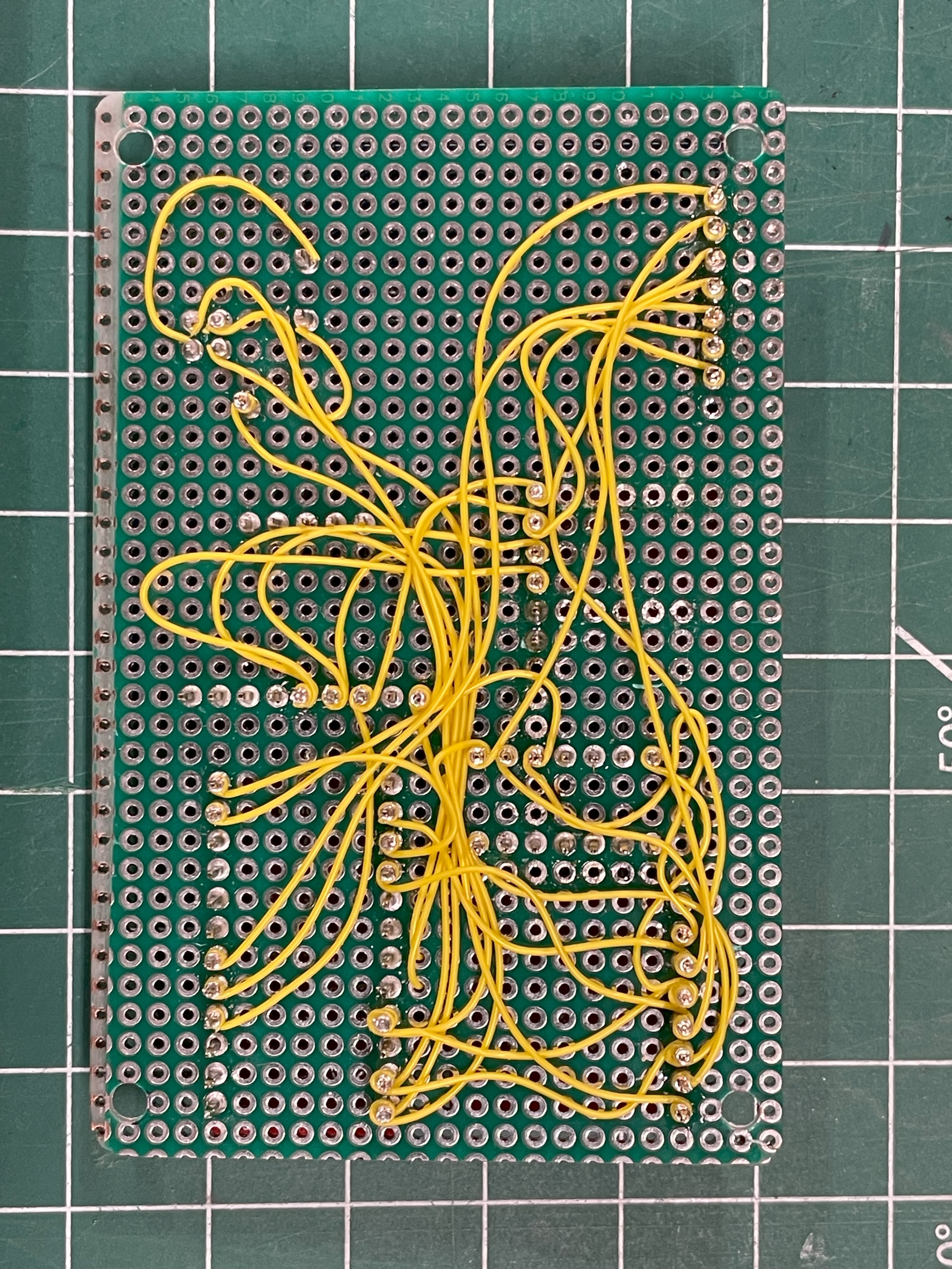
The flight controller hardware has gone through 4 revisions over the 15 flights. It does not make sense to lay out a PC board until the design stabilizes, so I build hand wired prototypes. The first three prototypes used the single row bus type solderable proto boards, but the 4th revision added more breakout boards than would fit on a single row layout, keeping the same size board used in the earlier versions. So I used a plain hole array proto board so parts could be placed over the entire area of the board. It is hard to do point to point soldered wires with multiple wired going to a single pad, so I decided to dust off an old skill, wire wrapping, which works well for multiple wires per post. The first board I wire wrapped I soldered after wrapping, being worried the wires would vibrate loose. But, after the first two flights, I needed to add a tri-state buffer, which required desoldering and replacing most of the wires. This time, I decided not to solder the wrapped joints to make it easier to make changes in the future. The controller has worked just fine for 3 additional flights with just the wire wraps and no solder. Wire wraps, done well, are much more robust than you might think!
Copyright © Thomas Fetter
2014-2026

To design the vertical trajectory control system software algorithms, it takes several mathematical models. The models are all described by differential equations, the equations of motion. The first two models model the forces and dynamics of the rocket. Specifically, these models describe how the rocket moves as a result of the rotation of the control canards. The first model describes how the rocket spins, or rolls about its longitudinal axis, in response to all four canards rotating by the same angle. The second model describes how the rocket tilts about its two lateral axes (pitch an yaw) in response to opposite pairs of canards rotating.
The third model describes the dynamics of the servo motor. The servo motor has dynamics of its own that impact the response of the control system, so those dynamics must be included in the control system design. In addition to the linear response of the servo motor, there are a number of nonlinear mechanisms like quantization and the motor dead zone, that can give rise to what are called limit cycle oscillations in the control system that are included in the servo motor model.
The last two models describe the complete control system. They include both the rocket dynamics models and the servo motor model. A control system uses feedback to control specific parameters in the system, in this case, the orientation of the rocket in space. Control system design is all about pole/zero placement to determine the dynamics of the system. Poles and zeros are the roots of the differential equations that describe the system. The control system design process involves either altering the locations of the existing poles and zeros of the system, called state space control, or adding additional poles, zeros, and gain, in a way that produces a stable and well behaved control system.
It is easiest to design a control system in the frequency domain, so the first control system model is a frequency domain model of the control system. Frequency domain models must be linear, so it does not include any of the nonlinear mechanisms. But it is used to design the feedback gains and any additional control loop filtering. Once the control system has been designed and shown to be stable, then the second control system model, the nonlinear time domain model, is used to evaluate the impact of all the nonlinearities on the stability and performance of the control system. The time domain model is actually a full 3D flight simulator with the VOS control code built into it. The time domain model shows the effects of wind and other perturbations and how the control system corrects for these. The model outputs are the same parameters that are measured or calculated and logged by the VOS system during a flight, so the model can be compared directly with the actual flight data.
The time domain model is also the way that the control code is actually implemented in the VTS system, so the time domain model is used to test the control code.
All of this will be documented in detail when I complete the technical papers on these topics.
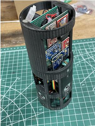
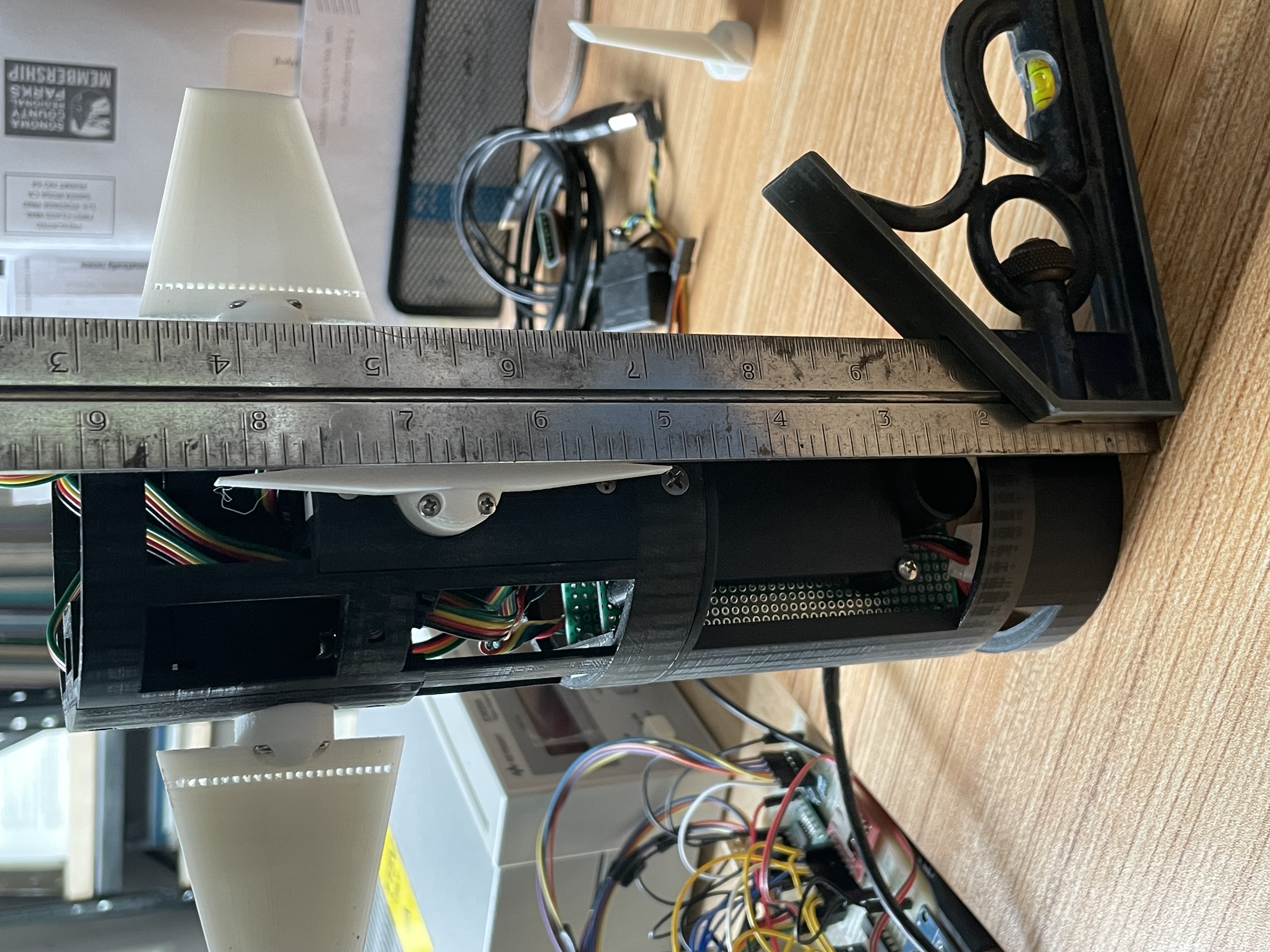
The control electronics board and power supply board slide into slots on ether side of the frame. The board holder frame and servo frame screw together in the middle. The servo frame serves as the retainer for the circuit boards. Separating the two units allows the boards to slide out of the frame from the front.
Aligning the canards (zeroing the rotation angle of the servomotors) using the special alignment canard - an elongated and stubby canard. This alignment tool and method can resolve 0.2 deg. The offset value is stored and applied by the Arduino VOS control code.